These are the major steps to be followed
· Creating the BizTalk application
· Configuring the ports
· Testing the application
Creating the BizTalk Application
Open Microsoft Visual Studio 2005. Select File->New->Projects. From the Project Types: select BizTalk projects and from the right pane select Empty BizTalk Project. Provide a folder location(C :/) for the project and specify a name for the project (UsingFunctoid) and click OK. We have to develop 4 artifacts:
· Input XML Schema
· Output XML Schema
· Map
· Orchestration
Creating Input XML Schema
Now right click on the project name and select Add->New Item. Select Schema from the left pane and Schema from the right pane. Provide a suitable schema name and give OK. Double click the schema on the solution explorer and the schema editor window appears.
On the left pane, right click on the root node and rename it (Form). Now right click on the renamed node and select Insert Schema Node->Child Record. Provide a suitable name (PersonInfo). Now right click on the child node and start adding field attributes by selecting Insert Schema Node->Child Field Attribute. The schema tree should look like this.

Creating Output XML Schema
Now right click on the project name and select Add->New Item. Select Schema from the left pane and Flat File Schema from the right pane. Provide a suitable schema name and give OK. Double click the flat file schema on the solution explorer and the schema editor window appears.
On the left pane, right click on the root node and rename it (OutForm). Now right click on the renamed node and select Insert Schema Node->Child Record. Provide a suitable name (Employee). Now right click on the child node and start adding field attributes by selecting Insert Schema Node->Child Field Attribute. The schema tree should look like this.

Creating Map
Right click on project name and select Add->New Item. Select Map and provide suitable name.
In the Open Source Schema, select the input xml schema that we created. In the destination schema, select output xml schema.
Go to the toolbox and from the Advanced Functoids, drag and drop the Looping Functoid to the design area. Perform the mapping as follows.
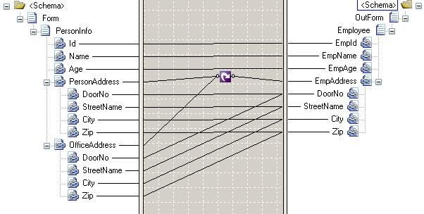
Looping functoid is used to combine multiple repeating structures in an input instance message into a single repeating structure in the output instance.
Creating Orchestration
Right click on project name and select Add->New Item. Select Orchestration and provide suitable name.
In the Orchestration view, create two messages with the following specifications
Message_1
· Identifier: InputMsg
· Message Type: Schemas->Input Schema
Message_2
· Identifier: OutputMsg
· Message Type: Schemas->Output Schema
In the Orchestration view, create two port types with the following specifications
PortType_1
· Identifier: Rcv_PortType
· Message Type: Input Schema
PortType_2
· Identifier: Snd_PortType
· Message Type: Output Schema
In the Orchestration Design Window, drag and drop the following shapes and set the specific properties.
Port_1
· Name: Rcv_Port
· Port Type: Rcv_PortType
· Port Direction: Receive
· Port Binding: Specify later
Port_1
· Name: Snd_Port
· Port Type: Snd_PortType
· Port Direction: Send
· Port Binding: Specify later
Receive
· Message: InputMsg
· Operation: Rcv_Port.Operation_1.Request
Construct Message
· Message Constructed: OutputMsg
Transform
Click Ellipses from the Input Messages property and from the Transform Configuration dialog box that appears, select Existing map. From Source select InputMsg and for Destination, select OutputMsg.
Send
· Message: OutputMsg
· Operation: Snd_Port.Operation_1.Request

Save the application. Generate a strong name key. Build and deploy the application.
Configuring the ports
Open BizTalk Administration Console. Expand the nodes and arrive at the newly created application. The orchestration appears in the admin console. Now we need to create Send and receive ports.
Creating Receive Port
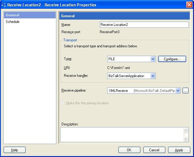
Right click on Receive Port and select New->One Way Receive Port. Provide a name and select Receive location from the left pane. Select new from right pane and provide a name.
Select FILE from Type and click Configure. Browse for the receive folder location and type *.xml in file mask.

In Receive pipeline drop down box, select the XML receive pipeline.
Creating Send Port
Right click on Send Port and select New->Static One Way Send Port. Provide a name.
Select FILE from Type and click Configure. Browse for the receive folder location and type *.xml in file mask.
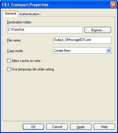
In Receive pipeline drop down box, select the XML Transmit pipeline.

Configure the application and start it.
Testing the Application
Drop a *.xml file in the receive location specified while configuring the receive port. The file is pulled by the BizTalk application and the output *.xml will be sent to the out location.
Sample Input File
<ns0:Form xmlns:ns0="http://UsingFunctoids.InputForm">
<PersonInfo Id="Id_0" Name="Name_1" Age="Age_2">
<PersonAddress DoorNo="DoorNo_0" StreetName="StreetName_1" City="City_2" Zip="Zip_3" />
<OfficeAddress DoorNo="DoorNo_0" StreetName="StreetName_1" City="City_2" Zip="Zip_3" />
</PersonInfo>
</ns0:Form>
Sample Output File
<?xml version="1.0" encoding="utf-8" ?>
<ns0:OutForm xmlns:ns0="http://UsingFunctoids.OutputForm">
<Employee EmpId="Id_0" EmpName="Name_1" EmpAge="Age_2">
<EmpAddress DoorNo="DoorNo_0" StreetName="StreetName_1" City="City_2" Zip="Zip_3" />
<EmpAddress DoorNo="DoorNo_0" StreetName="StreetName_1" City="City_2" Zip="Zip_3" />
</Employee>
</ns0:OutForm>